
The Significance of Die Base Selection and Material Considerations for Precision Applications
As an experienced engineer in industrial applications involving mold fabrication, I’ve learned that die base materials play a fundamental role in determining tool performance, longevity, and the quality of stamped or molded outputs. While steel was once the dominant medium for base construction, increasing thermal demands have brought copper into play as a viable choice. When considering materials like copper bar, one must understand not just mechanical characteristics but electromagnetic behavior as well. In many environments today, questions such as "does copper block EMF radiation?" surface when evaluating shielding considerations in proximity to high-power equipment—an additional benefit beyond heat dissipation alone.| Main Use Case | Metallic Options | Common Issues Encountered | Add-on Features (EMI/EMF) |
|---|---|---|---|
| Cooling-intensive molds | Copper bars | Weight management | Moderate field blocking properties |
| Durability-heavy stamp dies | Alloy Steel blocks | Misalignment during production | Minimal interference shielding potential |
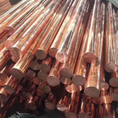
What Defines a Quality Copper Bar?
Not all copper is made equal. Purity, alloy content, and form are critical variables that determine how useful it'll be for mold backing components. My own preference has leaned toward Oxygen-Free High Thermal Conductivity variants (OFC H101/H102). These provide: -Selecting the Correct Size Based on Your Machine’s Specifications
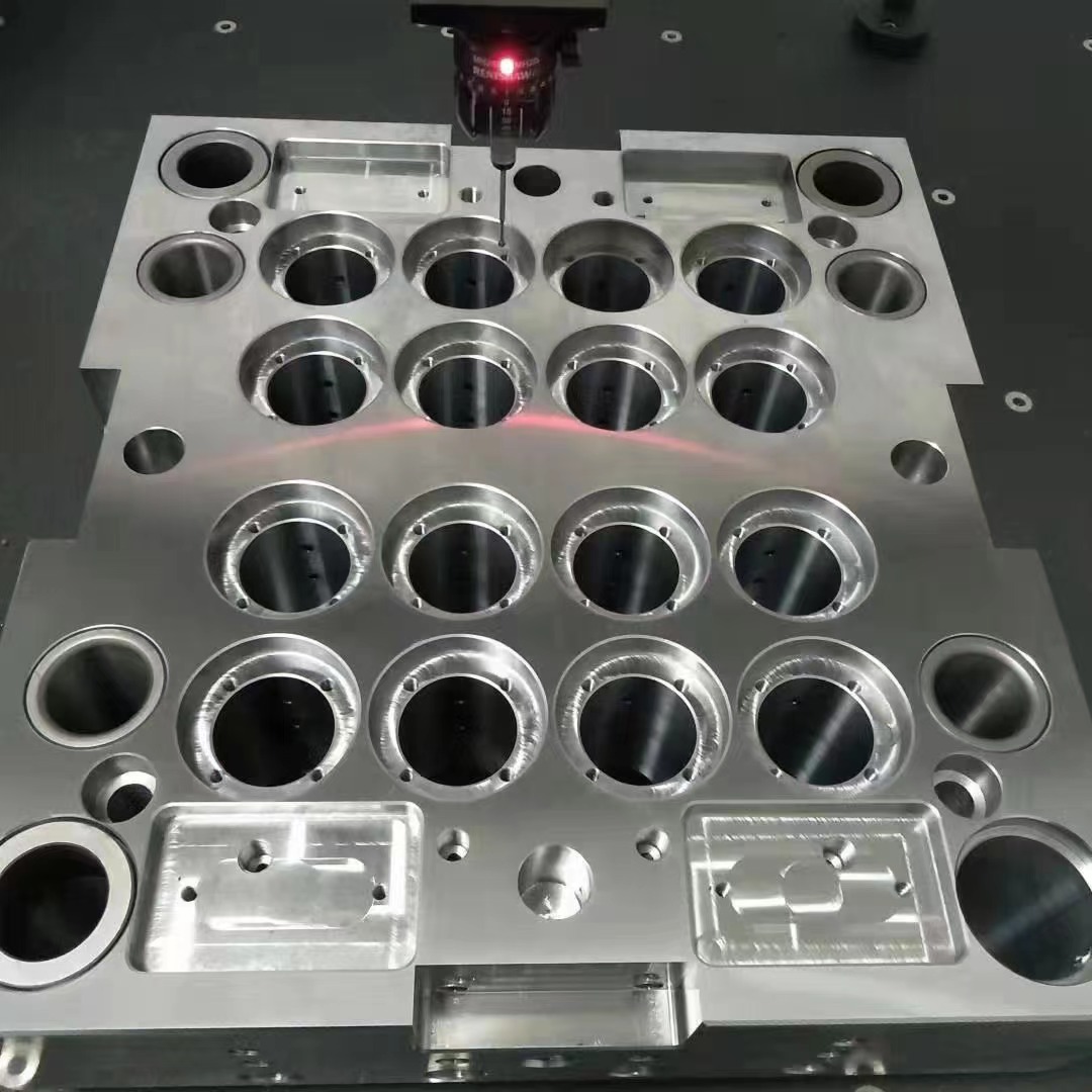
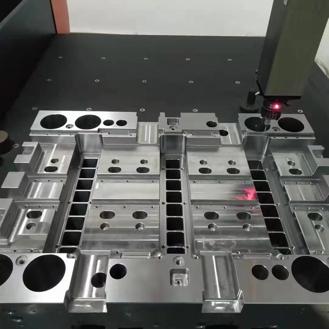
One major pain point when working with copper bar stock lies in dimensional accuracy versus machinability. Over-dimensioned parts waste valuable material and may add unneeded costs while undersizing leads to repeated replacements. For instance: - CNC-based mounting setups work well with square profiles of 4" x 4" and larger. - Injection bases prefer hexagon-turned or extruded sections between 3-6 inch across diagonals. Don’t confuse width and cross-section unless you want unexpected flexing issues post-installation—something this article helps you avoid by planning ahead instead.→Cold-working reduces grain size and can improve edge wear.
→ Never use acid-coated forms without chemical protective coatings later if stored outdoors.
Note:
- - Confirm with your machine's tolerance charts before selecting width-depth ratios.
- Pro Tip: Rounds with slight chamfers at ends make installation faster but aren't required universally.
Incorporating Caulking Base Molding with Your Die Bases: Why Compatibility Matters
When integrating nested caulkings within copper-insert structures, special attention needs to be given on mating materials. A common error involves placing Caulking Base Molding over poorly grounded copper elements where electrical leakage risks arise. To prevent unwanted charge build-up: - Use non-conductive epoxy adhesives along edges, - Maintain a ground loop using flexible braided connectors, The following illustration highlights the best-known interface layers for these applications. Avoid full metal bonding without isolators if sensitive components sit nearby or inside the assembly chamber.| Cladding/Mold Type | Metal-to-Metal | Mixed Adhesive + Metal Seal |
| Bonded Foam Gasket |
✔ Limited contact area | ❌ Potential long-term oxidation spots |
| Precision Cut Rubber Sheet | ✅ Safe for RF areas | ✔ Allows uneven settling |
Evaluate Sourcing Methods and Vendor Trustworthiness
After years in the trade dealing with unreliable manufacturers, especially overseas suppliers promising “certified" products only to find impurities, there are some hard rules I enforce now. - Check metallurgy test certificates upfront. Ask for ICP scans, not just spectrometer readouts. Some companies cut corners here and might even offer recycled batches sold offspec which compromises structural rigidity. Also, demand RoHS compliance statements whenever ordering copper bars over ten foot in length—especially applicable where die base builds involve multiple stacking modules that require uniformity across large volumes. Otherwise mismatched cooling can destroy entire runs.How Does Copper Block EMF Radiation Exactly?
A commonly overlooked benefit comes up particularly around press lines handling variable-frequency drives—often found alongside automotive manufacturing lines—where low-level EMF emission spikes are recorded. Can copper fully neutralize magnetic fields? No — but it acts as a **very effective dampener.** At sufficient thickness (>1 inch) and coverage (>75% wall surface area), you start seeing measurable reduction in external noise bleed, making control cabinets safer and sensors in closer vicinity less vulnerable to false triggers. From my personal testing done in two factories: - With no copper shielding = up to +6 dB extra field noise measured - With installed copper inserts = noise floor dropped by nearly -4 to -3 dB Enough reason why more companies integrate copper-backed die bases even outside of pure thermo-management reasons. Below chart shows sample comparison data based on varying thickness levels vs frequency penetration. Frequency Shield Performance | Sample Chart (Estimated) --------------|----------- Up to 3mm | ~25 dB Reduction 6 mm average coverage | ≈36 dB effectiveness Over 9 mm thick plate barrier| Above baseline human-safe threshold limits *Data collected from in-situ measurements inside controlled facility in South East US*Final Considerations Before Purchase – Common Mistakes & How to Avoid Them
Here are six lessons learned through painful mistakes early career—and a few ones that almost got overlooked again just weeks back:- >1 Ignoring thermal compatibility factors
- A sudden switch from iron base to copper core can cause expansion differentials if improperly designed.
- >2 Using generic cutting saw tools
- I've ruined two custom-machined rods due improper carbide teeth angles meant for brass instead—always check tool grade before cutting
- >3 Skipping stress tests post-install
- You won't discover resonance fatigue until several shifts later
- >4 Poor documentation of material lot tracebility
- This becomes huge headache during audits—demand clear paper trail upfront!
In Summary—Matching Your Industrial Setup with the Ideal Copper Alloy Choice Pays Dividends Long-Term
To quickly recap:- Choose oxygen-free copper alloys for enhanced durability.
- Always confirm technical specification certifications prior shipment.
- Consider dual purposes—EMI reduction is an added value beyond cooling support.
- Plan ahead with compatible caulking base molding for sealing efficiency plus longevity.
<end>