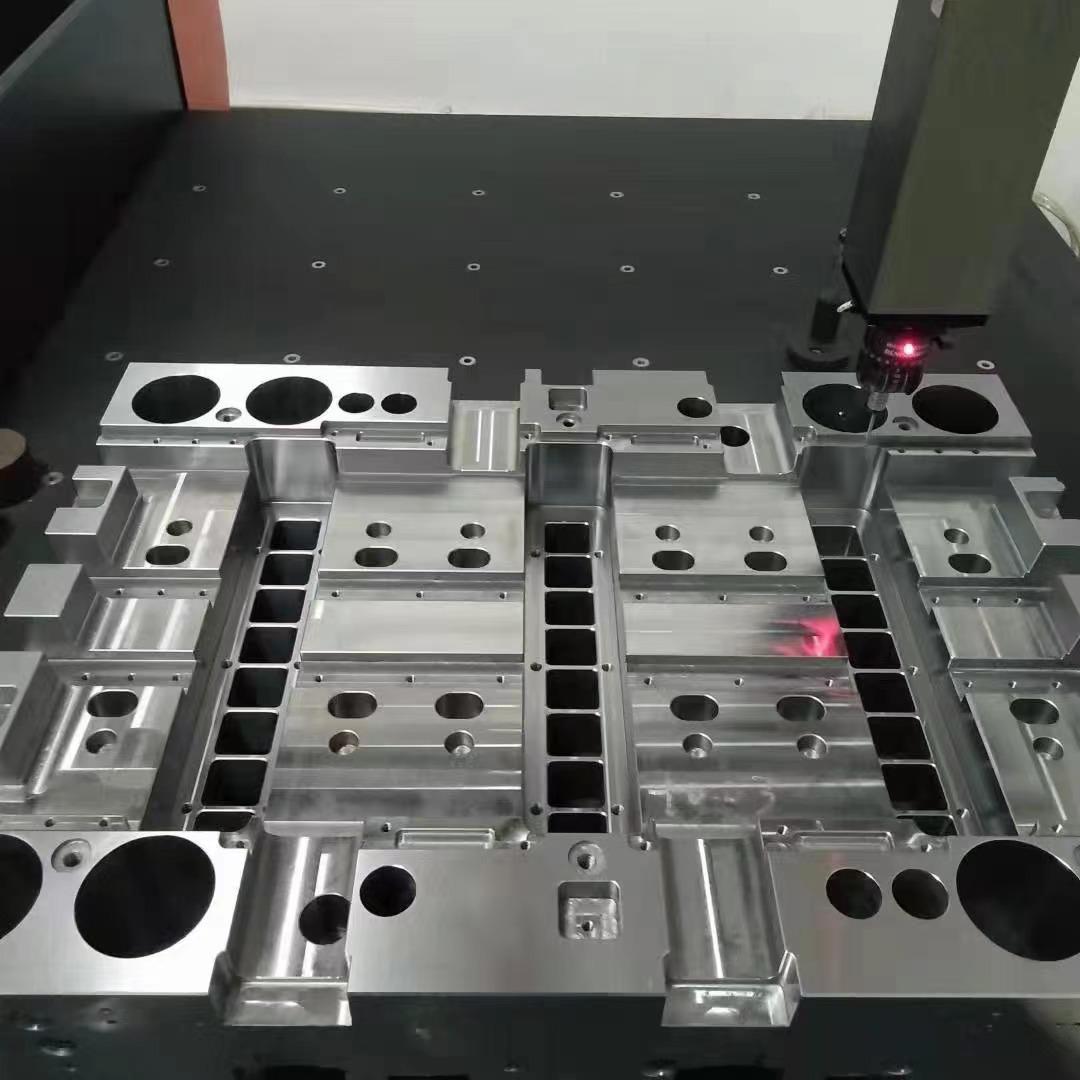
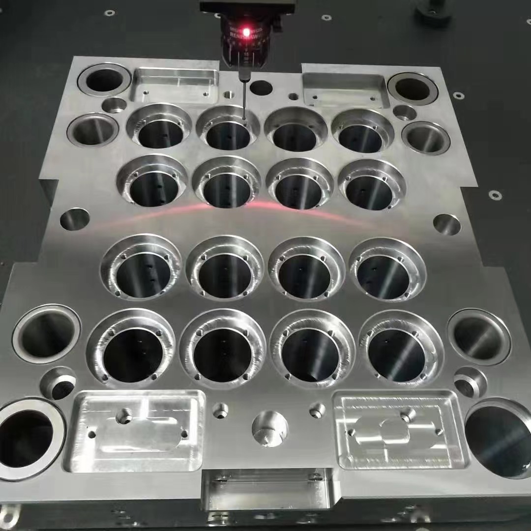
The Importance of Material Selection in Mould Base Engineering
One aspect I cannot stress enough is how crucial it is to make the right decisions about material selection when working on a Mould base project, especially concerning thermal characteristics. For years, I've dealt with issues related to hot spots, differential cooling, and uneven heat dissipation — all problems stemming from poor thermal planning.
- Potential for part warpage due to inconsistent heat transfer
- Material deformation as a consequence of uneven pressure distribution
- Degree to which surface imperfections develop over time
Lately, however, one component has gained my particular attention — the use of copper blockers, sometimes known as heat sinks or thermal diffusers. They're a small but significant improvement that can really transform a tool’s long term reliability, particularly under high production rates.
| Mould Component | Primary Thermal Concern |
|---|---|
| Cavity insert | Localised overheating |
| Mold base | Inefficient heat redistribution |
How Copper Blockers Enhance Thermal Dissipiation
I’ve found through multiple applications that incorporating copper into a standard mold assembly significantly boosts conductivity. Unlike standard alloy steels — like 4140 chromemoly used frequently for structural parts, copper allows much faster lateral movement of heat away from concentrated pockets.
A good example I worked on was a medical-grade housing component, requiring extremely fine tolerance control (typically +/- 2 μm). By inserting a 1 mm thick copper plate between cavity backing plates and mounting plates, I saw up to a 32% improvement in cooling response during cycle tests. What surprised me wasn’t the change in absolute numbers; it's how consistent results looked throughout production runs, especially over thousands of cycles.
If your system involves a Vinyl Cove Base Molding profile (used in architectural components, decorative molding applications), temperature control along the outer surfaces becomes paramount since they often retain more residual heat than planar sections — something we’ve had issues addressing effectively in the past without extra water circuits, which tend to over-complicate tool builds. That’s where integrating these conductive inserts makes a tangible difference in reducing both setup complexity while boosting output quality.
Common Installation Configurations
The trick to successful implementation isn't just placing the copper blocker somewhere near heat-sensitive geometry; you also have to position them optimally in terms of spacing and proximity. There are two primary layouts I see most commonly utilized:
A dual-plate layout sandwiching the core/cavity set inbetween
Slightly staggered arrangement around areas showing thermal hotspots, as confirmed via infrared analysis
Troubleshooting Thermal Anomalies During High-Cycle Runs
You don't always get perfect stability in the first few production phases of any custom build. In cases where internal channels were otherwise unable to fully manage excessive heating, I observed visible streak lines forming around ejection mechanisms—this was specifically linked to insufficient cooling capacity at critical junction points.
- Reworked circuit routing using angled micro-drilling methods
- Revised mold structure to integrate additional blocking plates
- Elevated insulation in regions prone to cold bridging (often behind sprue openings)
“In some situations, merely adding more coolant pathways did not help—what changed performance metrics was how efficiently conducted energy got rerouted."
Selecting the Right Copper Alloy Type
I'm often asked, “Why copper?" The answer lies largely within metallurgical data available through standard industry references, especially those published by companies likeCarpenter Technology Corpand CDA (the Copper Development Association).
| Alloy Name | Thermal Conductivity [W/m·K] | Main Benefits |
|---|---|---|
| Copper-101 | ~ 398 W/m.K | Highest conductivity rating amongst castings, suitable for ultra-fine toleranced mold types |
| BeCu Alloy 670 | ~ 125 W/m.K | Balances electrical/thermal properties without compromising hardness |
Note how even Beryllium-Copper offers lower conductivity values than pure Cu101 – yet it’s widely employed because of better corrosion resilience and moderate machinability traits in many molding environments, especially plastic injection scenarios dealing with PVC, polycarbonate compounds, or aggressive additives.
Integrating Modern Techniques with Conventional Approaches
Over time and several revisions to earlier techniques adopted in our company, I’ve begun adopting new design tools including CFD-based mold simulation softawares (Ansys Fluent,Siemens MoldFlow Insight et.al.) that let us predict how effective certain configurations would be in practice, prior actual tool manufacturing phases.
This allowed a lot more flexibility, for instance, being able test out placement ideas like offset stacking of copper sheets, interleave thin stainless barriers, experiment with layered hybrid assemblies — approaches I previously considered impractical before implementing digital prototypes saved valuable testing cycles in real life conditions.
- Coupling CAD simulations to validate initial assumptions against practical limitations.
- Mimicking real-world heat gradients by setting varying boundary temperatures across simulated blocks.
- Ran iterative tests with parametrized variations — thickness, alloy blend percentage etc.
| Simulation Approach | Description |
|---|---|
| Cu-block integration in 3D CAD | Digital layer mapping of copper and steel components inside SolidWorks |
| Cooling flow analysis | CALculated temp distribution patterns with and without enhanced blocking structures |
Balancing Economic Viability Against Manufacturing Long-Term Gain
Now I admit, copper costs significantly more than ordinary die-steel materials. But when factoring total lifespan ROI on molds, I started to think less about direct expenditure per unit cost and more about long-term gains from reduced rework downtime or lower repair frequencies during maintenance periods.
For an average sized production job (~120mm x 180mm base plate dimensions), installing say two Cu-plate modules can add ~$400-$500 to the tooling estimate, however if we reduce reject rates from roughly 3.7% down to about 0.9% after integration, then overall savings become pretty obvious when running over 350+ hours weekly in continuous operations environments like automotive plastics sectors.
And honestly speaking - there aren't too many other methods which can match similar performance benefits this affordably. Unless perhaps you’re looking at laser-sintered inserts, though those tend toward even steeper pricing tiers for niche production demands.
Summary
To wrap things up — I’ll reiterate how copper blocker systems have shifted paradigms in conventionalMould base engineering: Not only do they address fundamental thermodynamic inconsistencies within tooling units, but their integration brings notable enhancements in cycle stability, defect reduction, and process consistency levels required to meet stringent modern fabrication criteria — particularly vital today in industries reliant upon micro-tolerance integrity like medtech and semiconconductor component domains.
- Thermal diffusion plays a bigger role in mold efficiency than generally acknowledged by traditional builders;
- Copper blockers enable rapid dissipation of trapped heat without requiring expensive retrofitting or extensive coolant redesign efforts.
- Even thin layers (as little as 1 mm thick copper plate ) provide measurable improvements, suggesting that space constraints may no longer limit adoption options;
- Newer simulation techniques allow accurate virtual modeling prior to manufacturing execution;


