
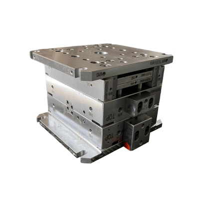
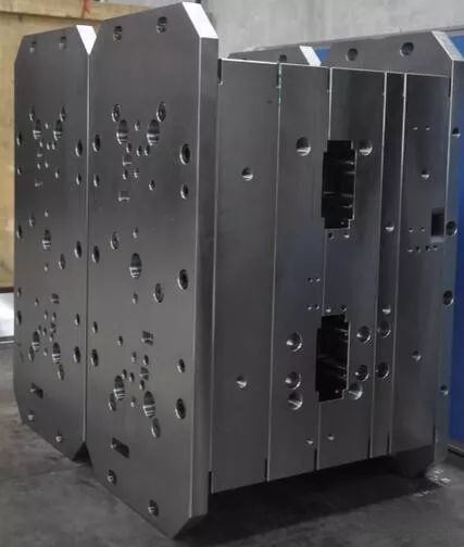
Over the past few years I’ve worked extensively with metal components in manufacturing projects ranging from mold making to CNC machining. One of the most important parts that always gets discussed early is the die base.
Why Your Die Base Matters
I often get asked, “Is the die base just a platform for everything else?" While that's partially true — it’s way more than that. Choosing the right foundation affects tool longevity, alignment stability, and final output precision. If you go cheap on this step (believe me, I tried once) it ends up costing your entire timeline.
How Copper Comes In to The Picture
If your setup relies heavily on thermal transfer efficiency like EDM processes or injection molds using water line coolig — you start looking into different materials. That’s when the idea of block(s) of copper show up.
While brass or hardened steels dominate mold cavities — there are niche scenarios where copper excels. Think heat dissipation zones, conductive cores – sometimes even structural inserts made of high-conductivity copper blocks tailored precisely in the block-of-copper phase during fabrication.
One time I chose regular mild steel inserts over solid copper alloy blocks, big mistake. My thermal imaging tests later revealed uneven hotspots — and guess what came out of that? Warped part geometry — no bueno.
When A2 Steel Isn’t The Full Solution
Of course A2 Steel remains one my favorites: great edge retention, moderate toughness and machinability — don’t come near D2 unless you’re hunting deep wear resistance. But here’s something you’ll discover fast as you work longer:
- You might be designing a system that cycles between hot and cool rapidly;
- You may not be dealing solely with shear stress or impact but also electrical or thermal needs;
- Sometimes weight plays factor in moving stages and automation integration.
In some molds for hybrid polymer-metal parts, we ended up placing copper alloyed die shoe bases because they provided better dynamic load balancing under thermal swings vs traditional steel setups.
Possible Material Comparison Table for Selection Purposes
| Thermal Conductivity | Hardness (Rockwell) |
Weight Factor (per unit area) |
Corrosion Res | |
|---|---|---|---|---|
| Steel - A2 | 37 BTU/(hr.ft°F) ⋄ | 60-62 RC ⋄ | Moderate | Good* |
| Block of Copper Alloy CDA 110 | ≈223–416 BTU/hr.ft°F)* ⨁ | ≈ ~ 90 HB ** | Heavy | Low |
What if I'm doing Block Modding Instead?
If modders like you are custom building hybrid copper-based supports around a primary A2 framework, pay attention:
I've done quite a few die conversions myself where I replaced lower plates of an A2 structure with pre-cut blocks of copper inserts — mainly for faster thermal cycling inside plastic molds that had sensitive cavity structures needing constant flow.
Common Reasons Why Die Base Design Shifts To Copper Use Include
- Faster heating or cooling cycle demands (not all systems wait);
- Easing thermal expansion mismatch within complex material layers;
- Bypass standard aluminum limits while avoiding higher cost materials.
- Retrofitting legacy systems for conductivity upgrades without major reworks.
Pro Tip For Those Who're New: If going hybrid copper insert routes, never weld copper into non-compatible steel directly — use transition pieces! Otherwise crack risks double in heat-affected joint areas especially with rapid cycles involved!
How to Install Base Cap Moulding — And Coppe[!] Integration Points
A weirdly common issue comes when people assume installing decorative trims at bottom (base cap moulding) has no influence over underlying performance. Let's talk real world experience again.
Years back, I had designed a dual-purpose edge guide frame integrating copper-coated base strips acting as both guiding runners and minor static control layers inside automated robotic welding booths.
The problem started only when installers slapped standard wood-based molding trim directly onto those metallic guides. Static built over days caused intermittent misfires. Not the end but a headache to track down after launch phase!
Listed steps below help you plan safely:
- Evaluate ground path continuity through copper section prior to mounting base cap molding trim;
- Dry-fit everything without adhesive yet! and verify contact spots;
- Incorporate insulating barriers where conductivity must stop;
- Avoid using natural rubber padding under heavy metallic copper parts—risk for long term pressure creep or deformation issues;
Final Note: Selecting The Right Match from Baselines down to Block Level Changes
There isn't any universal best. Every shop environment differs based on what type of operation frequency, required tolerances, tool life goals or production timelines you're facing daily. What I’m trying here though is to help give you frameworks for better material decisions especially where conventional steel setups aren’t giving you desired results.
- Use Standard Steel Like A2 Only If
- No dynamic or shifting duty conditions — especially related to temperature, pressure, movement cycles etc. Long-lasting edges & wear profiles are your top concerns here,
- Opt for Copper Blocks (or Copper Linings Inside Base Structures) IF
- You require quick temperature response in molding or tool heating — especially in short-cycle or thermally active settings.
- Pure Mechanical Environments Are Usually Safer Using A2 Steel Based Systems With Minor Inserts
To summarize: I cannot count how many failed trials I had by assuming generic base standards will suit every condition — don't make same mistake. Always consider the function first before choosing base materials, including the strategic insertion or installation points of a good quality block of copper in appropriate cases can literally prevent overheats or costly maintenance rounds downstream.