
The Essential Guide to Mould Base Selection and Its Connection with High-Qicality Copper Cathode in Manufacturing Processes
When it comes down to creating high-precision industrial products, two elements that often go unnoticed by non-engineers but remain critical in production design: the mould base and copper cathode integration. As a manufacturing consultant involved heavily in injection moudling sectors, I have seen many instances where overlooking minute details—like which type of metal alloy or mounting plate to select—can impact not just output efficiency, but end product durability as well.
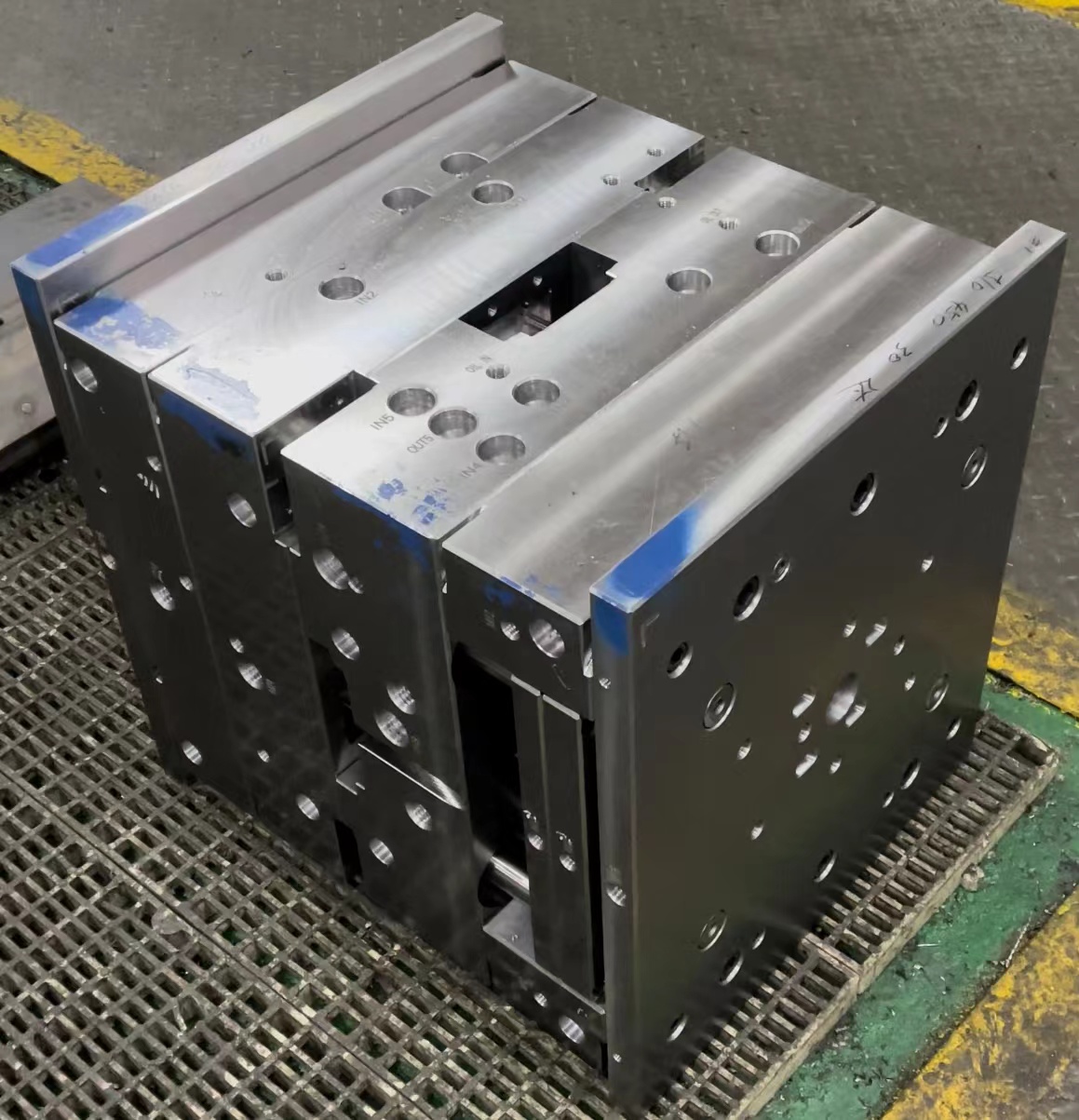
The Role of the Mould Base: Foundation Before Function
To put it simpley: your mold is no better than its platform. Without a strong **mould base**, any inconsistencies in alignment during injection can cascade into catastrophic outcomes. In my personal projects, one mistake I made several years ago—using an aluminum-based support instead of standard steel on a long-running run batch—ended up in costly re-machining, not to mention lost time.
- Durablilty: The core benefit when selecting a proper steel or tooling-grade alloy-based structure.
- Coolant compatibility: Ensuring optimal thermal regulation for part consistency
- Precision machined components for reduced misalignment issues
| Metal Type | Tensile Strength (MPa) | Density (g/cm³) | Thermal Conductivity (W/m.K) |
|---|---|---|---|
| Steel Mold Base | 400 - 800+ | 7.9 | 50 |
| Aluminum Base | 186 - 550 | 2.7 | 221 |
| Copper-Inlaid Base Plates | Variies by alloy mix | 9+ | 300-400+ |
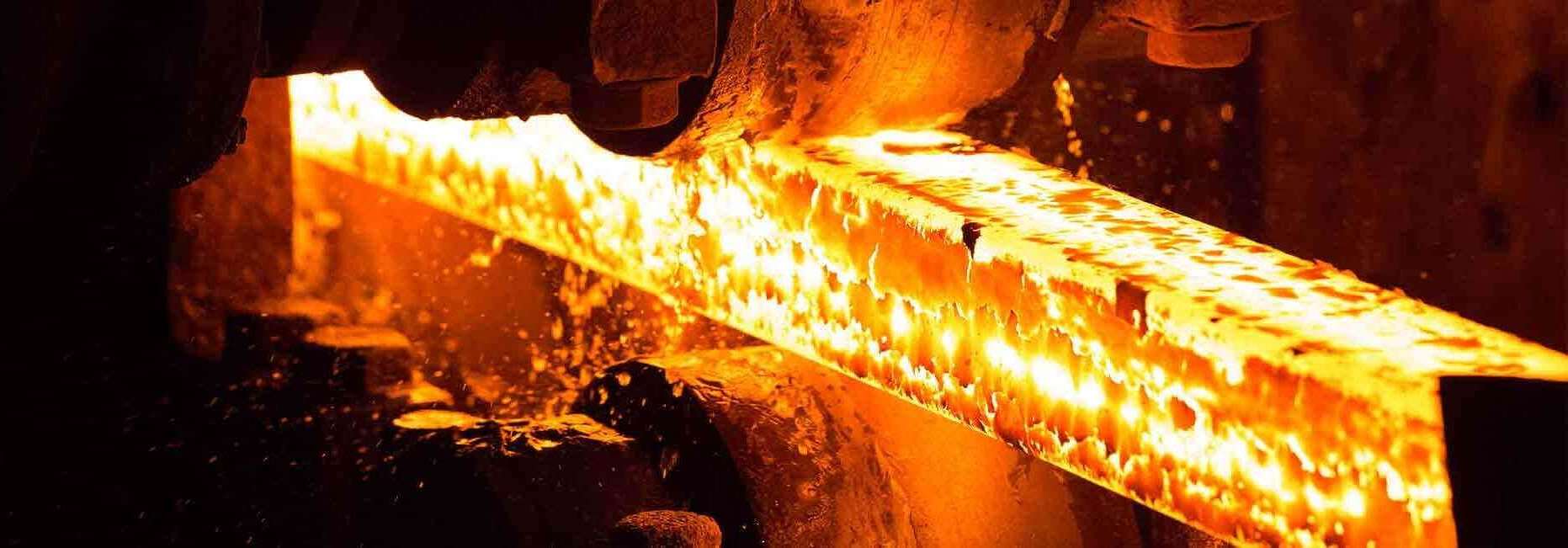
Why Copper Cathode is a Game-Changer
This was one of those lightbulb moments—after learning why copper is so often used not merely because of its conductibility, but due to it being more consistent thermally. If you want even heat transfer within the cavity—say you're producing micro-electronic casings—that’s the element you rely on. Now, the question becomes: where does the copper cathode fit into a traditional injection set-up?
- Acts as the primary material source for EDM cutting in cavity work.
- Much lower electrical resistance helps shape fine-toleranced grooves with high stability
- Incorporating copper alloys directly impacts cooling uniformiety, especially in multi-impression mold builds.
Finding Harmony Between Mould and Medium
There's been many projects where clients asked me to retrofit their old steel molds using copper-backed inlays without changing core dimensions. At face-value? Smart cost-cutting move—but it works best when you know how to pair the right kind of plating. From what i've found: if you’re aiming for sub-zero tolerance runs (think automotive connectors), mixing HCHCR tool steels alongside copper-rich bases is ideal, albeit not the most budget friendly at first glance.
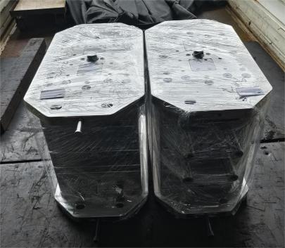
Practical Takeaway When Installing Base Cap Molding
You'll encounter Base Cap Molding in precision encasement manufacturing lines far more frequntly than you think. Especially common across custom plastic molding firms. Installation involves some delicate handling; however there’s a step-by-step method worth highlighting here based on field-tested experience, from my early training at a Japanese engineering workshop back in Kyoto.
- Selecting proper clearance tolerances before pressing anything in place—don’t underestimate expansion under heating
- Use a modular alignment gauge; it might seem old-fashioned, but digital systems sometimes skew measurements over multiple cycles.
- If manual assembly required, keep torque settings tight around threaded areas—use Loctite to reduce risk of vibration loss post-installation.
How to Measure and Cut Base Moulding With Precision
Even with CNC machining becoming industry-standard today—especially in Tier-I suppliers across the States—some smaller workshops still use handheld tools for low-volume production parts. I remember assisting with a small electronics job outside Detroit where a single faulty measurement threw off six hours of milling work because someone missed alignin the clamps evenly after recalibratin a vise setup.
So how do we avoid this? Through process-oriented methodology. Let’s look at five basic tips when dealing with manual cuts, which are also useful as fallback checks even if automation exists:
- Always start calibration from a fixed point—one corner of a jig, rather than arbitrary X=0 coordinates every single time. It creates a reliable reference baseline each day regardless of temperature swings.
- Use carbide tip cutters even if costs a bit more per unit; tool wear is dramatically lower when carving hardened plates like P-20 grade supports.
- Rough-cut slightly inside intended dimension line before finishing cuts, prevents stress cracks and improves long-term integrity
- Apply light coolant spray—not heavy flooding—as sudden changes from rapid cooling induce hairline fissures along edge points where mold will flex during injection
- If possible—and budget allows—always invest in digital laser projection overlay devices when working in large-format molds
Missteps I’ve Learned from Over The Years
Here are a few hard knocks I personally learned from managing international mold fabrication operations:
- Undercutting edges when installing side-core pins led to leakage and warping later—I ended replacing three entire units just to fix poor pre-processing habits.
- Choosing lower quality copper for short-run jobs resulted in uneven surface erosion. That was an ugly lesson when a key client halted shipment of hundreds of units halfway due to internal blistering
A Quick Checklist: Before Starting Production Run
Here's something you can quickly check through before starting:- Mold clamped securely, all fastening points verified double-check for play or imbalance
- All runners aligned vertically—no cross-thread or lateral bending detected after last cleaning cycle
- No visible signs of oxidization in exposed copper cathode rods
- Vent channels checked—particularly important when deep wall sections need full evacuation for pressure management.
- Last recorded cavity temp reading below threshold allowed for specific material resin—this can vary depending on PP, PETG, PVC etc.
Final Words: Connecting the Molds to Quality Control
There isn't one approach to get it “perfect," since conditions differ widely—from medical plastics to high-strength polymer composites. However understanding the interdependencies between materials selection (especially the role of **Copper Cathodes**) paired effectively with durable mold platforms ensures better control throughout your lifecycle. For instance, one major project with aerospace casing involved integrating graphite-coated inserts to allow for easier demolding while maintaining tight specs on radiused joints—without a properly cooled, layered steel/mixed-alloy mold system with embedded copper cathodes running along internal runners—it’d never passed FAA approval phases on the third round, which is something we had barely enough lead time on anyway! If there’s a golden takeout: Treat the mold base not like a supporting character. Treat it like part of your QC framework from Day One. **Conclusion:**Whether you manage your own manufacturing or oversee procurement teams, mastering the linkages between high-quality cathodes and mold construction is pivotal in ensuring repeatable, scalable success. My advice after navigating dozens upon dozens of complex build cycles worldwide is straightforward yet rarely applied thoroughly: spend more upfront on your base infrastructure—specifically around mould base rigidity and material compatibility of copper cathode components—and reap downstream savings you wouldn't believe. After all, building with intentionality means fewer emergency redesigns—and more happy engineering conversations than crisis ones.