
Die Base Manufacturing with High-Quality Tool Steel Plate – Durable Solutions for Precision Engineering
In the precision-driven world of die manufacturing, selecting the right base materials and tool steel alloys can make or break project outcomes. As an engineer immersed in advanced production design, I've spent a considerable portion of my career exploring durable material solutions—none as reliable yet often underestimated as **A2 steel plates** in crafting high-performance die bases.
A solid die base doesn't merely offer support; it’s a cornerstone of stability and accuracy throughout production cycles—from prototype to scale manufacturing. Let's walk through the engineering logic and hands-on rationale that guide decisions around **tool steel plate**, especially when dealing with performance-oriented scenarios in modern workshops.
Understanding Die Bases & Their Core Role in Manufacturing Tools
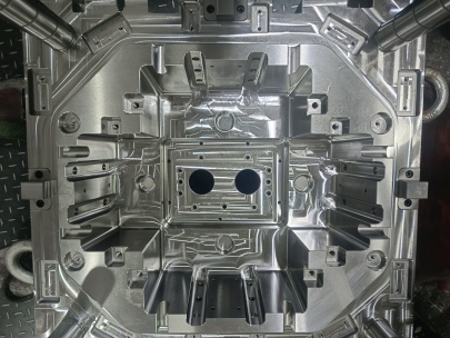
If you're relatively new to fabrication circles—or perhaps returning to them—you're likely wondering, “What is a die base?". Essentially, this term represents the foundational component upon which dies are built. It provides alignment rigidity, load distribution, wear resistance, and acts as the backbone in punch and stamping setups where micrometer-level precision cannot be overlooked.
- Mechanical anchoring point for dies during high-impact use cases.
- Serves as reference plane for consistent setup reproducibility.
- Dampens vibrations generated under heavy industrial press loads.
Selecting materials for die beds must account for prolonged durability amid dynamic mechanical stresses—making **tool steel plate** like A2 one of the industry's leading candidates over more common alloy varieties.
| Tool Alloy | Typical Use Case | Impact Resistance (Rating) | Hardenability Range |
|---|---|---|---|
| O1 Oil Hardening | Knives, chisels, cutting tools | Low-Mid | BH Rc 55+ |
| D2 Cold Work Steel | Piercing dies & extrusion molds | High | BH Rc 50-60 |
| A2 Steel Plate | Diverse general mold supports | Mid-High | Core: Bh Rc 48 - Shell 58+ |
How Does A2 Grade Stand Against Common Workshop Challenges?
Let's not treat this lightly: tool failure due to improper alloy selection could halt an entire plant’s daily productivity for days—and sometimes longer when rework gets complicated or replacements delay timelines by weeks.
A2 tool plate, a member of ASTM A681 cold work steel series, delivers a sweet spot between moderate machinability (as opposed to higher carbon steels), good toughness, decent thermal distortion behavior post quench hardenining, and acceptable corrosion resistance if treated well (especially with chrome or nitride overlays where required). This combination makes them ideal starting blocks, especially in mid-range stress toolbed configurations without needing full-hardened exotic composites.
A Typical Machinist Perspective on Pre-Hard Plates
"If I need to drill multiple threaded inserts into a fixture bed while minimizing bit damage—no heat-treated A1 will cut it. Give me some pre-A2 block stock any day before pushing CNC toolpaths at the edge." — A Senior Setup Engineer from Ohio (who refuses HSS anymore unless he's drilling wood).
This real talk from the field sums up why many practitioners prefer softer but uniform grain-structured alloys pre-hardened to ~ Rc 35/38. The trade-offs? Slower polish times but better weld integrity. That's a deal maker when repair becomes inevitabile rather than optional maintenance.
Practical Guidelines for Handling Gold Plated Copper Inserts – Avoiding Die Damage
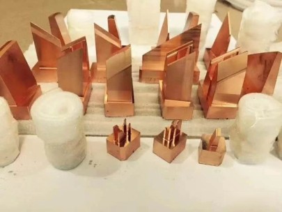
We’re going deeper now—not just talking about core construction anymore. Let’s say you’re making a custom composite die insert with gold-plated copper zones (why would anyone need gold there? Well maybe they do… for RF cavity applications in medical devices, semiconductor molds, whatever reason floats your tech fancy... ).
Placing such reactive metals inside traditional stamped tool pockets poses integration hazards—especially oxidation concerns or unwanted galvanic effects between differing conductive components if improperly insulated within assembly gaps.
RULES WHEN DEALING WITH GOLD PLATED COPPER INSERTS:- Airflow ventilation near junction should always exceed ISO 5 clean level specs to avoid dust buildup on non-metal surface areas
- Copper needs a bonding agent barrier beneath electroplating stage to control interlayer delamination risks
- Gilding process temperatures shouldn’t surpass critical transformation phase points in the underlying toolplate alloy structure, else warping follows.
- Avoid acid dips if possible; use citric acid-based polishers or microabrading paste when fine finishing prior plating step is required.

Choosing Between Flame vs Induction Heat Treatment Paths Post Machining
Now, once the structural layout seems stable (like when I align my base to mill 200 lbs worth of mounted die guides and punch blocks accurately within 4 micrometers across four axis)—comes heat treatment.
This choice isn't purely academic—its financial and risk-based impact affects whether a shop goes under budget with quality output, versus getting caught chasing costly failures down unplanned paths.
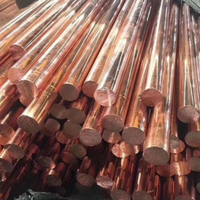
Two common approaches dominate current workflows: Flame or Induction based post-treatment processes after shaping out slots and cavities from initial billet stock of tool steel plate A2-grade standard sizes (typically 1"-1 ½") sheets used widely today across U.S. metal shops..
Flame Hardening Pros + Negatives- Limited depth penetration; useful only where low wear area focus required
- Risk of un-even hardness gradients depending operator skill/exhaust management conditions during heating cycles
- Requires post-stress relieving operations—common source of distortion
- Uniform magnetic induction ensures predictable phase transformations even with uneven cross-section parts
- Toughness retention stays significantly higher vs direct oxy-propane heating methods
- Pretty easy to integrate inline via PLC-controlled automation steps these dayd
Evaluation Framework: When A2 Stops Being Enough & Better Steels Arise?
The problem arises not with how good A2 Steel really performs (because truthfully—it's excellent given proper handling). Rather where the line gets blurred is understanding exactly under what parameters this particular option falls short, warranting more specialized material exploration elsewhere.
Let’s build myself (and others) a small self-audit matrix here: Are you seeing recurring failures caused by either...
- Sudden edge chip fractures in corner grooves?
- Faster wear patterns than previous jobs under similar loads? Like twice as quick abrasive pitting appearing despite no coolant changes or lubricity loss observed?
- Misalignment creep in progressive stages, leading to poor ejector fit or slide jam issues in sequential forming operations
- An unexpected temperature fluctuation that compromises your final temper consistency mid-run?
Nailing Die Plate Finishing Steps to Minimize Rejections Later On
The devil hides in detail—polishing counts among those critical ones you overlook at your peril.
No amount of high-end heat treatment fixes a poorly prepared base surface riddled with machining striations and residual grind patterns left behind after initial slab prep cuts—this increases fatigue-induced crack formation probability manifold under cyclic stamp loading pressures over weeks’ usage spans, even in controlled climate workshop environments.
My checklist includes:- Cross check every visible contour path using 3x magnifier lens inspection prior deburring.
- Blend all sharp radius transitions to smooth tangential flow via diamond lapping paste.
- Confirm perpendicularity across opposing surfaces using angle cosine caliper method—never laser plumb.
- Last stage wipe pass should incorporate oil-film barrier protection ahead long-term storage packaging steps (I swear by CRC Heavy-Duty Marine Coat for offshore applications where rust starts faster)
Conclusion & Strategic Outlook
Making a die base may seem routine on first glance, yet every seasoned tool room hand can vouch otherwise. Whether opting to go for traditional routes of forging and flame quenching, adopting induction-enhanced temper lines or integrating precious material plated components inside complex multi-layered assemblies—you’ll find A2 Steel still plays anchor where cost meets complexity head to head.
I’m not afraid to experiment newer steels—I have done that plenty. But there are still days when nothing beats working with a tool steel plate that machines evenly with predictable dimensional behavior during draw, responds reliably to controlled heat inputs and holds up under sustained load trials month on end with no surprises.