
Uncovering The Real Perks of Using Copper Bar in Mould Base Builds For Maximum Industrial Efficiency
I’ve seen a lot in manufacturing and machining, and one thing I know from experience — choosing the right material for mold bases is more important than most people realize. Lately, more and more machinists like me have been turning to Copper bars, especially where thermal performance or conductivity matters. But why copper over other standard mold materials? What benefits does this metal truly offer when building industrial-grade tooling systems? Let’s go beyond theory — this is about real use, real results, and some hard-earned field knowledge.
Why Consider Copper Bars at All?
I used to work on plastic molds that required precision heat control. When parts cooled unevenly during production runs, problems started creeping in – warps, sink marks and longer cycles.
That's when it hit me — aluminum conducts better but can't take as much abuse under certain pressures and high temperature zones compared too well with what we tested next.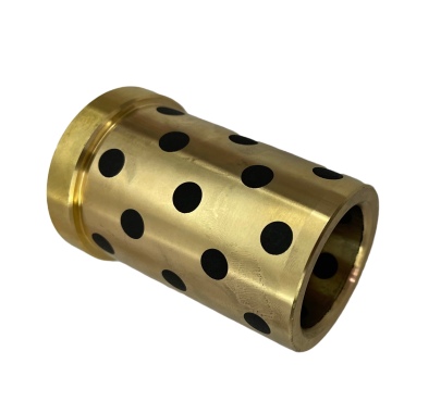
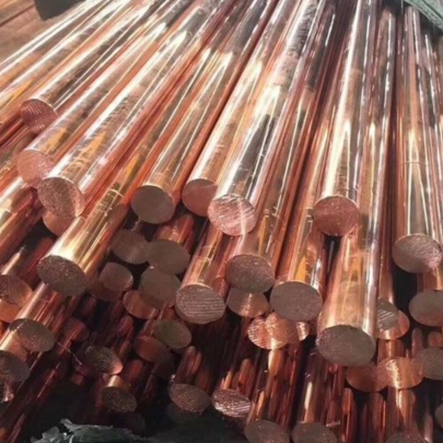
Copper bar became our alternative material. Sure, not everyone recommends it, but there were clear upsides:
- High Thermal Conductivity - Moves heat way better then steel/aluminum alternatives
- Anti-Friction Characteristics — great in moving joint sections within molds that require smooth slide surfaces daily usage over years
- Erosion/Corrosion Tolerance Better than other common non-copper alloys under long run operations conditions
Where Can Copper Be Actually Implemented Inside a Mold Base?
You're not going to swap the entire frame over without thinking, no doubt. There are places though in any typical Mould Base assembly setups where you actually need specialized components instead generic ones.
- Punch holder areas in forming press setups — reduces friction buildup quickly through conductive cooling effect
- Sprue Bushings made from cast or machined from stock copper billet
- Insert pads that support core pieces needing rapid heating & cooldown phases in same operation (especially for thermoplastics like PPA / PA12 resin)
The Downside Of Traditional Tooling Metals
It’s easy to fall into habits using whatever alloyed steel block came from vendor this month. Yet in many cases, old standby solutions miss crucial advantages offered even via secondary material inserts made of highly refined copper bar stocks:| Characteristic | Mold Steel Alloys | Copper Bar Based Parts |
|---|---|---|
| Thermal Dissipation Rate | Average-to-Poor unless water channel optimized | Excellent naturally via molecular lattice |
| Weight / Unit Volume | Heavier, up to 7–8 g/cm³ average vs pure Cu’s 8.96 g/cm³ | Barely impacts overall tool base total weight except in heavy load applications. Slight downside sometimes but tolerable |
| Draft / Slide Performance | Fair | Much Improved surface finish when coated or properly plated before install inside mating cavity blocks |
Practical Uses for Large Blocks and Custom Shapes
No article like this could skip talking about big block Chevy copper head gaskets.
While I'm mostly into tooling myself (molds specifically), I once built out a side line selling custom racing cooling upgrades for engines using high-conduction inner core sheets taken straight off leftover mold grade stock materials including wide flat slabs of reclaimed .400 inch thick pre-annealed copper bar offcuts we didn’t scrap. Some shops were happy sourcing them because it improved inter-block sealing between aluminum heads and cast iron block interfaces when torquing was perfect. You get far fewer hot-spots cracking open under stress after long dyno pulls if your base structure maintains tighter temp ranges across combustion cycles—very similar benefit applied in large molds dealing cyclic injection heating phases followed cooling sprays in automated cell.Installation Notes Every Engineer Needs to Know About Working With Soft-Metal Injections
- Clean Your Tools Before Use – Don't mix carbide drill bits used earlier on carbon steel projects; copper gets gummy and clogs if not drilled with special high rake bits set at specific feed speed settings.
- Think About Lubrication During Finish Work -- Air mist doesn't help. Need to add synthetic oil spray system during deep plunge routing or EDM cuts otherwise burring worse.
- If using multiple plates stacked vertically make sure your locating keyway fits tighter. Unlike hardened steels soft Cu tends expands quicker along X axis with minimal pressure. Preheating all parts to room warm helps match dimensional tolerance easier versus leaving half at freezing temps due warehouse location
- Also note corrosion risk if you work in humid plant regions — store copper parts sealed away under vacuum nitrogen pouches or apply protective wax coatings prior storage longer duration beyond six weeks. Rust might look ugly but oxidation spots on these elements ruin fit accuracy later so plan ahead.
Performance Results Speak Louder Than Theory Alone
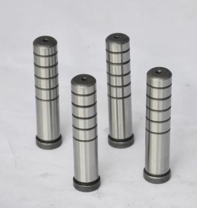
At this point, let's talk actual data — I ran side-by-side mold tests with three separate builds back in early ‘23 using nearly identical BOM specs except changing guide bushings, ejector pins and minor insert supports to either conventional mild steel, phosphorous bronze insert or raw cold-rolled Cu-OF 99.5% purity bars (Copper Bar 1/2" round profile mainly). I kept track of cycle consistency numbers, defect rate trends every day, plus maintenance log entries tied wear levels found week by week. Take a look at table showing general findings:| Setup Type | Downtime per Week(HRS) | Total Output (parts) Month Avg | Reject Percentage | |
|---|---|---|---|---|
| Variations 1 | 3.5 hrs | 7800 | 6.2% | |
| Variation #2 | 2 hrs 38 min average | 9123 pcs/month approx | 3.6%-4.2% | Copper-based components integrated moderately across critical thermal joints |
| Last Version | Largest reduction = only one scheduled hour | Topped previous bests — averaging near 10K per cycle test phase | Stable at under two perecntage point | Incorperated highest density copper component inclusion possible including larger 3mm diameter ejection pin cores. |
Harnessing Its Full Potential Requires Smart Choices
Here’s what I learned after trying this in my own setup for several seasons now: - Always source certified OFHC quality grades if possible, avoiding lead impure varieties since those cause micro cracking under extreme mechanical cycling situations - Try pairing copper elements in mold zones adjacent active hydraulic cooling paths to multiply thermal effects further. Even minor differences here matter big-time - Keep re-evaluation logs each production batch. If you see sudden jump in part variation percentage — chances are your primary copper component(s) may be experiencing degradation faster in one spot than another area - Never compromise on post-maintenance inspections just 'cause copper parts look newer after repeated uses compared to other metals; wear patterns aren't always visually obvious!In Summary... So, what really works ends up being practical application matched material properties. The role of **copper bar** inside modern-day Mould Base constructions definitely isn’t mainstream yet outside niche sectors such as aerospace composites fabrication, die cast precision runners production and complex blow mold manufacturing where managing internal temperatures becomes essential rather optional choice. Whether its 4x8 copper sheets welded directly into mold frames or large cross section copper bars shaped to exact contours of complex mold core pockets, I’ve experienced first-hand gains you just cannot fake in spreadsheets alone. From lowered rejects, higher production speeds, smoother motion interfaces inside tool bodies—the evidence keeps growing. If you want serious longevity combined with top-tier process controls…consider taking another honest hard look toward what pure unadulterated metallurgy offers through advanced usage of copper alloys. Your next step: start with small integration points, monitor carefully for performance changes—and let data speak, not hearsay or assumptions. Keep optimizing, and keep questioning.