
Mold Base and Block of Copper: Essential Components in Precision Manufacturing
In precision manufacturing, small design details can make all the difference in the quality and functionality of the final product. One aspect I often encounter during mold design projects is the importance of choosing between a **mold base** or solid materials like a **block of copper**, especially when heat dissipation becomes critical.
When working on high-performance molds for industries such as aerospace and automotive, I rely heavily on thermal properties that ensure optimal production. That’s where materials like **copper alloys**, along with precise edge detailing like **Base Triming Rounded Corners**, come into play.
The Role of Mold Base in Tooling Setup
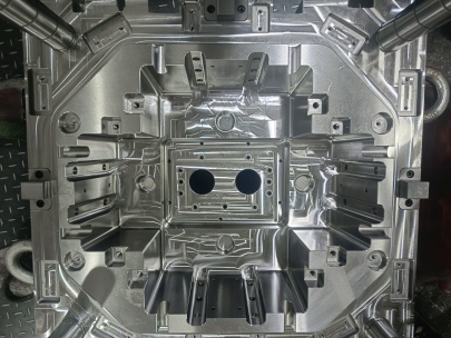
Most injection mold builders know that the **mold base** serves as the foundational platform for all cavity and core inserts. It holds guiding bushings, ejector pins, sprue bushings and provides a structural foundation that allows modular changes over time.
A pre-built mold base—either standardized or fully customized—offers a balance between speed of setup, durability, and long life performance without needing excessive reengineering from project to project.
- Supports cavity, core & runner insert mounting
- Incorporates cooling lines & ejection mechanisms
- Modular system saves cost/time over building everything from scratch
Cutting back to raw metal blocks like copper usually only makes financial sense with smaller or high-conductive applications, such as rapid-cooling cores inside plastic molds.
Selecting the Right Block of Copper
When extreme conductive requirements enter a job—especially during high-volume cycles—I find myself turning more often towards blocks machined directly from solid materials like a **block of copper**. This decision comes not only down to thermal conductivity (which can surpass even aluminum), but also the ease of localized cooling and complex shape carving possible.
| Material | Thermal Conductivity (W/mK) |
|---|---|
| Steel (P20) | 30-35 |
| Aluminum | 160-180 |
| Copper | 350-400 |
Machining a Waxed Block of Copper
I once worked on an intricate project using a waxed block of copper, a process typically involved in casting operations requiring tight tolerances without losing conductivity benefits. The wax acts as an initial mold material in investment casting scenarios, ensuring dimensional fidelity after molten flow cools and hardens correctly.
- Lay out wax structure over desired pattern form
- Dip into ceramic slurry, creating hardened layers
- Heat to melt-out inner wax (lost-wax technique)
- Pour molten copper alloy into void and cool
This method gives engineers flexibility when designing highly irregular cavities, while allowing retention of superior heat transfer behavior within final parts.
The Importance of Base Trimming: Focus on Rounded Corners
One of my recent pet peeves during post-casting has been overlooking **base trimming** practices—specifically corner radius application. Rounded geometry on edges doesn’t just affect aesthetics. It significantly affects mechanical stress relief, mold flow dynamics and fatigue life at contact points where abrupt geometry transitions happen during operation.
- Rounded corners improve resin flow patterns in thermoplastics injection
- Minimizes air trapping under shear forces inside the chamber
- Enhances overall part uniformity by evening pressure distribution
If corners are too square—without slight fillet adjustments—it creates potential failure points where microcracks start showing under thermal cycling tests. Even polished copper edges won't survive long in dynamic molding if these principles aren't adhered to.
Case Study: High-Conductive Molds for Automotive Prototypes
Last year, our R&D unit designed molds to accelerate prototype builds of automotive bezels requiring internal light pipes coated inside molded housings.
To achieve even surface textures under hot melts (over 315°C melt temperature in PEEK polymer grades), our lead technician decided on partial copper core segments integrated directly into a standard P20 frame base. This let us test different configurations without redoing entire setups. After several test runs including both conventional steel-core sections and custom-cut waxed blocks of copper, thermal images validated quicker cooling by 18% in average cycle duration—an incredible outcome we almost didn’t anticipate.
Design Considerations When Choosing Material Types
You should consider multiple parameters—not just raw conductivity figures—when opting for whether standardize on existing mold bases vs. fabricating full copper-based tooling. Budget limitations may prevent widespread use of expensive raw stock materials across large-scale mold sets—but smart compromises do exist.
Key points to evaluate:
- Production volume needed over lifespan
- Budget allocated to raw material inputs
- Tolerance needs in final molded pieces (precision level req)
- Thermal sensitivity or need for accelerated cooling features
- Maintenance frequency expectations during lifetime use
Remember that rounded features and trim adjustments (Base Triming Rounded Corernes) might save you money by reducing post-finishing costs and extending mold durability beyond typical break-point cycles under high-volume production demands.
Integration Techniques and Best Practices
If you plan to mix copper modules into existing steel frameworks or integrate a block-based segment into larger systems, be very meticulous about interface sealing methods—both physical gaskets or metallurgical coatings—to avoid leakage and unwanted corrosion over extended operating periods.
- Pre-bake molds above dew point humidity prior use
- Select non-reactive epoxy sealant between dissimilar materials (avoid galvanic erosion in water cooling systems)
- Maintain tight geometric specs during assembly (within 0.02 mm per GD&T blueprints where needed).
Conclusion
Making decisions between utilizing **mold bases** versus crafting components directly from raw **blocks of copper** hinges largely on application requirements, material efficiency and long-term operational goals.
I’ve grown accustomed over years in industrial design and tool maintenance to weigh factors including thermal dynamics, mechanical fatigue limits, production volumes—and don’t overlook subtle details, such as those in Base Trming*(*probably meant to spell rriming). Those rounding touches matter. In several cases, switching up to copper blocks allowed faster prototyping cycles without degrading part integrity or increasing waste outputs due to uneven mold flow behaviors. Integrations work best when executed systematically—with special attention paid not only to material selections but also interface handling methods that extend serviceable equipment longevity beyond usual industry benchmarks.
So next time you’re weighing options for precision toolmaking, maybe give your current workflow a rethink—not only from a budgeting perspective but from performance tuning standpoint. Small investments in superior-grade copper segments could yield outsized results across mold reliability, output speeds and energy consumption metrics.