
The Ultimate Guide to Choosing the Right Copper Blocker for Your Mold Base in Injection Molding Engineering
I've been working in injection molding engineering for over a decade, and let me tell you—Copper blockers are one of those critical components that many designers overlook during the initial design phase of the Mould base. If your mold base isn't properly engineered, even minor thermal inefficiencies can lead to major production problems. In this guide, I’m sharing my hands-on experience about selecting the right Copper blocker, when it's needed vs cavity steel, how geometry plays into heat transfer, and some common pitfalls I personally ran into early on my journey.
Understanding the Role of a Copper Blocker in Mold Base Design
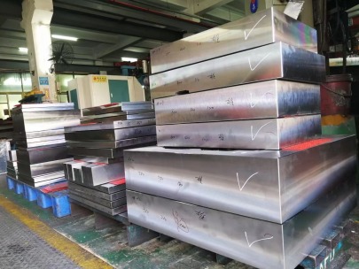
Copper blockers are essentially square or custom shaped plates made from oxygen-free copper alloys (common ones being OFHC or C103).
If you’re working with high-precision molds like those for aerospace plastics or medical-grade resins—using Tile Base Molding systems—you’ll find heat removal efficiency matters a hell lot. And here’s the thing: unlike cylinder-based coolant lines, copper blocks provide direct conduction where water cannot go.
| Cooling System | Thermal Efficiency (%) | Material Type |
|---|---|---|
| In-line channels | ~45% | Steel core with standard cooling lines |
| Copper blockers | >72% | OFHC - copper block inserts |
| baffles & bubblers | 65–72% | Cored-out tooling solutions |
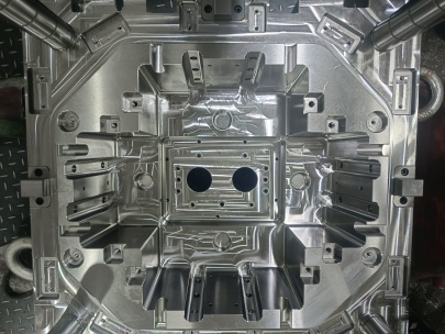
How Mold Bases Integrate Copper Blocks for Cooling Performance
You can’t separate mold cooling optimization without taking into account the overall design of your Moud base—or shall I put that better: the mold plate framework itself. That includes everything from core/cavity plates to support structure underneath.
A typical mistake is assuming that all Molding applications benefit equally from Tiled Mold Base setups using Copper Blockers. In fact—especially at lower shot quantities or small batch runs—the ROI diminishes fast because machining a copper insert isn’t just expensive; the setup also takes extra time and testing.
Selecting Copper Thickness and Dimension Based on Thermal Demand
If we think about real examples—for instance: say you are trying to cool a square plate of copper with 50.0 cm sides used as a parting line spread cooler across two half mold stacks...
- Determining correct depth penetration relative to part thickness profile
- Finding surface area to weight proportion per alloy grade (be cautious with brass alternatives)
- Ensuring enough space exists between adjacent components inside ejector plates or core lift mechanisms
- Evaluating cost of replacement after extended exposure to aggressive chemical cleaners sometimes present in molding environments
There are formulas involved (and they vary) but honestly: the key takeaway I found was that you can almost never oversimplify heat transfer analysis for copper unless you’ve got decades in field. It pays to simulate using FEM softwares—like Autodesk MoldFlow—even if only doing so helps identify weak links earlier than actual tooling stages allow.
Why Tile Base Molding Benefits From Using Copper Coolant Inserts
You might not be aware, cavity tiling approaches have surged lately thanks to modular manufacturing demands.
Here’s something to consider: With tile base molding configurations, maintaining equal cooling rates across individual segment tiles becomes exponentially difficult without thermal regulators built in—which copper blockers offer effectively due to its superior conductive index compared to regular mold steel (~2 times increase on average).
Main Points Supporting the Usage:
| BENEFITS | BUILD IMPACT |
|---|---|
| High thermal conductivity of copper improves cycle time by ~18% | Better temperature homogeneity in tiled mold surfaces |
| Faster cooling means reduced warpage risks in larger injection molded items (car bumpers, etc.) | Rapid dissipation lowers distortion risks significantly |
| Easier repair and replacement during life cycle maintenance phases of large-scale projects. | Makes upgrades faster due to modularity advantage |
Avoiding Costly Errors: When Not To Use a Copper Blocker?
This one hits hard—because I remember trying to use copper block inserts back during an early job. Big regret? Yes! Because I ignored application compatibility first before design logic, resulting in a costly misaligned insert weld, and multiple days down the gutter in debugging cooling line paths that wouldn’t sync up.
When not advisable:
To save money, try aluminum cooling blocks for prototypes, especially if full-volume production isn't confirmed yet. They’re easier to machine and still conduct much better than basic tool steel.
Fundamental Criteria When Choosing The Perfect Copper Geometry For My Projects
Let me walk y’all through the criteria list—since geometry determines so many other decisions including fit, cooling time impact, ease of machining and service lifecycle longevity…
- I always measure mold layout clearance—before anything.
- Make sure no bolt threads interfere once installed—especially with side ejection setups.
- Precision cut edges matter a great deal—if burrs appear after assembly, expect thermal resistance issues later on.
| Squared dimension range (width x thickness) | Expected Temp Drop | Suitable Applications | Max Shots/Tool-Life Cycle |
| 12x1 cm – Low density | -9° | Benchmark samples | ≈240 thousand |
| 20x2.5 – Mid Range Blocker | -15° | Bottle caps / small automotive interiors | Up to 1 Million |
| 30–45 mm thick w/different edge angles | > -20° | Medium sized containers, electronics casings | ~600 K + rebuild potential |
| Over 45 cm² size plate blocks | >>-30°+ | Jumbo packaging trays or heavy structural parts | Dependent upon alloy |
*Note values represent approximate outcomes; actual performance depends on system pressure flow balance, ambient air circulation and proximity to gate locations.
Conclusion: Balancing Practical Needs With Copper Block Advantages
The reality I found throughout my years of designing intricate Mold bases and overseeing large mold builds is simple: you don’t want copper inserted just for hype’s sake.
It should serve as intelligent thermal assist mechanism tailored to solve localized cooling bottlenecks. When combined within strategic portions of Tile base molds or layered into complex core designs needing rapid cooling feedback—it shines bright.
In most applications—whether I'm prototyping plastic bottle mold sets or industrial-grade enclosures with embedded heat traps—I rely heavily on copper blocks shaped accurately and tested in simulation beforehand to reduce surprises in trial runs.
A final word though—if ever choosing copper over traditional materials, know the added cost does justify over long-life cycles…just be mindful to plan accordingly. No shortcuts in material testing. Make every copper block count—and you will be rewarded with precision parts and satisfied clients eventually!
``` Let me know if you'd like to adjust content tone further or add more technical diagrams, images, or external citations for stronger SEO positioning.