My Personal Journey Into Die Base Mechanics and Copper Ingots
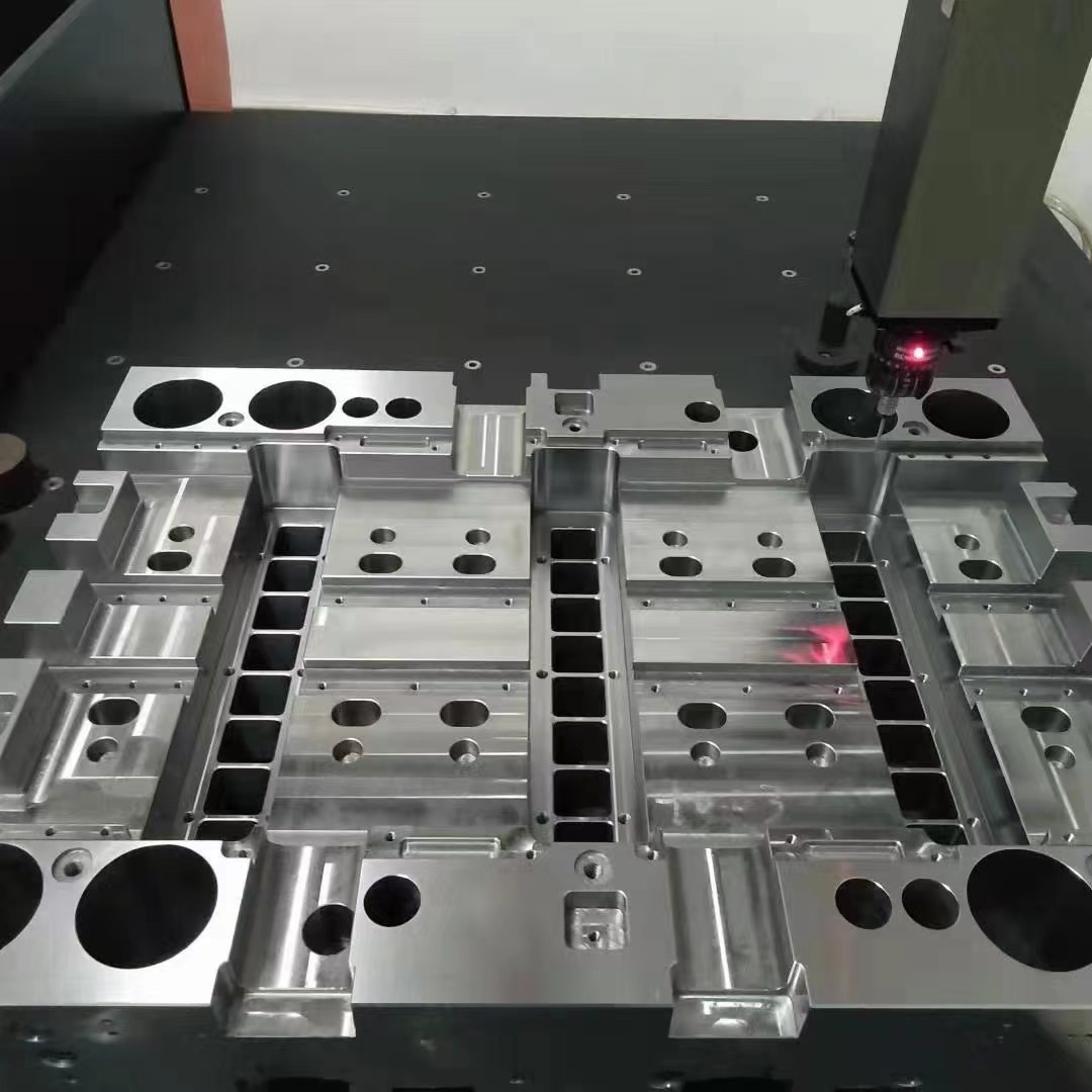
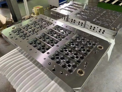
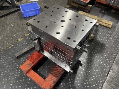
When I first encountered the term "die base," I assumed it had nothing to do with copper, but over time I realized how interconnected they are in metallurgy and mold design. As someone passionate about precision manufacturing and industrial processes, exploring the role of a die base—especially when linked to processing a block of raw copper—has become one of my most challenging yet enriching technical dives.
| Term | Description |
|---|---|
| Die Base | Support framework for stamping tools and molds |
| Raw Copper Block | Unprocessed metallic stock shaped for casting |
| Base Molding Styles | Variations of forming techniques used for ingot casting |
The Real Connection Between Die Base Construction and Raw Copper Stamps
I’ve often wondered why many toolmakers talk extensively about die bases when casting metals, particularly using high-melting ones like raw copper slabs. What surprised me was how crucial structural stability becomes once molten material gets poured at such immense heat levels. Without a proper support setup (i.e., the die base), any minor misalignment in base molding styles could distort an entire batch of processed copper ingots.
- Misaligned die plates lead to uneven stress distribution.
- Incomplete seals create porous edges.
- Material cooling rates vary due to unbalanced chamber geometry.
Common Base Molding Challenges with High-Conductivity Metals
Copper has this frustrating trait of being both tough on dies because of its high conductivity *and* malleable during phase transition points. From personal trials I've run, it seems the more complex your base molding style is, the more risk you run of damaging or deforming the final copper structure. My team even faced issues during the testing phases trying to use conventional press setups for creating intricate patterns on a large block of raw copper—we were getting incomplete impressions almost half the time.
A few things we picked up through experience:
- Selecting reinforced steel components for your die base matters immensely—aluminum doesn’t work as expected due to rapid fatigue
- Lubricant flow rate should adjust per casting speed; otherwise you might notice micro-weld points near corners
- Absorbent mold lining is often underrated. We tried a new ceramic blend mid-project, and saw significant improvements in edge definition of the finished blocks
Draft Considerations in Block of Raw Copper Manufacturing Setups
An important point no one really highlights? Draft clearance adjustments. Even tiny deviations here result in stuck blocks after solidifcation cycles. I had a test run where the copper failed to release because draft angles didn't factor thermal contraction properly—I lost nearly $3K that batch because of it.
In retrospect, a good guideline would’ve prevented all the waste. Here's what worked eventually: always ensure your angle compensates by at least +4% beyond mechanical standards to prevent post-cast friction lock-ups caused by cooling-phase distortion around base mold edges.
The Importance of Seal Design on Large Copper Ingot Bases
The term "copper block seal" started popping up when we were evaluating leakage prevention on multi-tier mold configurations. I learned real quick there’s not enough literature dedicated specifically to ensuring airtight interfaces when dealing with extremely viscous alloys like pure forms of copper. This was especially relevant since we noticed small imperfection clusters near junction lines where the die base connects into mold channels, suggesting inconsistent contact zones.
To give some context: here's what we changed mid-run, leading to a noticeable performance improvement
| Factor Changed | Old Setting | New Optimization |
| Gasket Type Used | Soft rubber inserts | Titanium-alloy composite joints |
| Seal Contact Area | .68 square inches | .93 with rounded profile extensions |
| Surface Pressure Application | Slight tension bias applied | Balanced force along entire mating face |
Lessons Gained From Copper Forming Failures I Actually Endured
No matter what simulation models suggest, practical implementation of theory often fails in the real production floor. Early on, we ran into porosity issues while attempting vacuum-assisted casting methods within the die bases used in copper fabrication. The issue came from trapped gases that couldn't vent through our selected seal types. It took me two weeks of sleeplessness to realize we weren’t monitoring internal air pockets properly due to overly sealed die enclosures—a harsh, albeit necessary lesson.
Conclusion: Building Confidence In Complex Casting Systems With Hands-On Experience
All of these struggles made it abundantly clear how interwoven die design elements like base molds and metal qualities such as those presented by handling a raw block of dense copper stock actually can be. Whether considering advanced die structures for mass casting operations or refining individual seal geometries, success ultimately comes down to mastering details beyond textbook theory—even with terms like base molding styles feeling like obscure engineering buzzwords at times, neglecting them cost me time (and cash).
If anything, let my mistakes teach you this: Never underestimate how vital foundational choices around die base selection impact outcomes involving conductive, heavy metal casting processes. And always test a full-range mockup set of conditions before scaling any copper block seal mechanism design.


