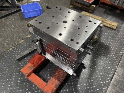
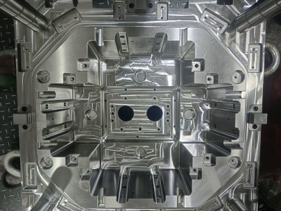
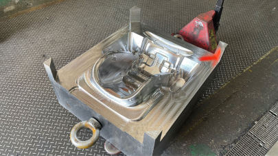
Copper Plate for Mold Base: Choosing the Right Material for Precision Engineering
As a mechanical engineer specializing in tooling and injection mold systems, I’ve come across numerous materials during the years. One particular item always gets my attention due to it's underrated importance: copper plates used within mold bases. While mold bases can utilize steels like P20, H13 or even aluminum alloys, there are situations where choosing copper makes all the difference. Today, I'd like us to go deep inside the role and rationale behind using both copper plate and sheeting specifically engineered for molds, how this impacts your design process—and what pitfalls most practitioners still fail to see.
| Brief Overview of Key Materials for Mold Bases | Metal | Heat Transfer (W/mK) |
|---|---|---|
| Copper plate | ≥85% | 401 W/m·K |
| Steel plate | P20 | 30-50 W/m·K |
| Aluminum sheeting | 6061 T6 Alloyed Aluminum | 170 W/m·K |
When Should I Even Think About Using Copper In a Mold?
The typical reaction I get from junior engineers? “Why on earth use copper, isn't steel good enough!“. Fair enough—if the goal was simply robustness against wear and abrasion. Steel holds well over time. However the real issue becomes thermal transfer properties. If your product has an aggressive cooling profile requirement (for instance high-volume thin wall parts or those made of high melting point plastics like PC, PMMA)—then heat dissipation speed matters *big league* more than standard strength ratings.
If you think that only applies for large volume jobs—it's worth considering again. Smaller batches with intricate cavity designs often benefit just as much. That's because complex internal geometries require highly efficient thermal zones which only copper’s high conductance characteristics can provide effectively compared to any conventional base metal otherwise considered acceptable today by many mold makers still locked into decades old techniques without understanding the science beyond empirical trial-and-error methods they inherited from predecessors who rarely ever asked why something works or if there exists a better way entirely—until they encounter issues like warping defects in molded items due poorly regulated temps across cavities which could've easily have been corrected earlier stages of project lifecycle if thought through ahead time before first production runs kick off and customer deadlines are fast approaching with potential scrap rate disasters looming near on horizon... sorry getting long-winded again let me step back briefly so i may reorganize train of thoughts better now moving next section
The Difference Between Copper Plate and Sheet Metals for Molding Tools
This is something people don't discuss nearly enough in academic circles but comes up every day in shop floor debates—so bear with my personal insight here:
- Thickness Matters – Plates tend to be above 0.18 inches while thinner sections would classify under “copper sheet" category;
- Structural Integrity Needs Vary – Plates support larger cavity blocks where significant temperature gradients persist between hot and cool spots in core area, allowing for localized conduction rather relying on full length of coolant channels for balanced temp control;
- Tier Cost Implication Is Major Divergent Axis Between Two Options;
Remember, while copper sheets help manage mild thermal fluctuations in mold base regions, actual insert holders and cavity backers often require thick copper block structures due to the intense localized heating they experience during shot cycles—even small variations in conductivity can impact part integrity especially during medical grade injection molding procedures. We’ll return later to explore that application deeper when examining industry case uses.
Thermal Properties That Justify The Cost of Copper Blocks
Let’s not kid ourselves, copper is pricey and harder-to-machine compare versus other mainstream alternatives. Still—many industries including aerospace, semis-conductor packaging and medical manufacturing continue opting copper mold structures at rates that seem increasing year-over-year despite inflation pressures pushing prices upward steadily since 2020.
Now let me drop one hard truth nobody likes to speak clearly—engineers frequently ignore data-backed material decision analysis because “we have existing equipment that handles common metals fine" which seems practical until sudden defect spikes appear post-mold qualification testing or during first pilot-run stage after commission and suddenly everyone's scrambling to find what went wrong in design handoff stage where thermal modeling didn’t account properly for localized hotspot buildup around ejection pins or gates due insufficient material performance under operational duty-cycles.
Key Takeaways Regarding Thermophysical Behavior Of Mold Tooling With Copper:
- Cu's high conductivity accelerates solidification rates → enabling tighter control over shrinkage parameters
- Cleaner release mechanisms reduce ejector pin damage risks caused by overheating-induced plastic bonding to cooler metallic contact surfaces (counterintuitive effect but backed up by recent studies showing up to 14% fewer sticking problems with optimized mold base conductivity);
- Draft angle compensation via material selection becomes viable strategy particularly relevant to amorphous resins whose molecular orientations respond sharply temperature-based flow path adjustments (e.g ABS, PC);
I’ve even seen cases where substituting select steel cavity backers with equivalent C110-grade pure electrolytic tough pitch (ETP) copper block reduced cooling times from projected average estimate (~35s/part cycle) all the way down to ~27.6 seconds—a saving nearly 8 sec/piece. Over ten thousand units run that equates 23 labor-hour gains alone—which offset material costs entirely depending usage conditions involved in such setup context.
Machinablility Challenges with Mold Copper Blocks
You’re not stupid for recognizing machining these metals isn't trivial. Pure copper is extremely malleable which leads work-hardening unless tooling paths programmed precisely, spindle speeds managed accordingly along chip evacuation pathways being uninteruptedly consistent throughout cut cycles whether facing turning or milling operation is executed.
| Material Type | Surface Roughness Before Finish Passes (µ-in) | Avg Machinig Hours/Unit |
|---|---|---|
| Free-Machning Brass Alloys C360 | ~63 µ-in | 4.2 hrs |
| Oxygen Free High Conductivity CuOFE | *Typical initial range of ~95+ pre-finishing cuts | 7.8hrs+ |
| Moldlite Series Pre-Alloy Copper Steel | ~55 pre-polish surface | About 4.7–5.6 hours depending alloy type selected |
The Reality Check On Availability Issues and Price Fluctuations in Recent Years
Yes. This needs addressing directly—since early 2020s global supply chains saw sharp disruptions and pricing hikes across multiple industries due geopolitical unrest affecting mine outputs alongside logistic bottlenecks.


