
Discover the Ultimate Guide to Die Base Manufacturing with High-Quality Tool Steel Plate
Hello! I'm someone who has spent over a decade designing and producing molds — from initial sketches to full production runs. One thing I learned early on is how **critical** it is to understand die base construction if you're serious about injection molding quality. Today, I’ll guide you through die base fundamentals, why the right materials matter — especially **tool steel plate** — and how components like copper affect your final design efficiency. By the time you finish reading, you'll see why small decisions in die engineering lead to massive outcomes downstream.
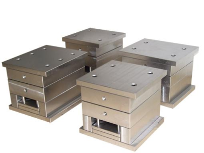
The Anatomy of a Quality Die Base Design
A standard mold assembly is made up of various components: cavities, cores, ejection systems, supports, guides, and most importantly…the foundation that keeps it all in place—the die base. Now, this ain't just two blocks bolted together. It's engineered for alignment precision within tenths of millimeters. And it’s usually where we specify high-quality material selection.
- Support plates : Keep cavity/core plates stable under extreme pressure
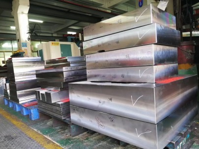
- A/B plates : Often CNC machined from solid tool stel slabs for durability
- Land area reinforcement : To stop warping or distortion under long-run use cycles
Why Tool Steel Plate Is Still My Go-To Choice (Despite Alternatives)
You may have heard folks talkin’ up carbon steel as a cost-friendly option or aluminum for fast prototype cycles. But let’s be real—if you want longevity under heat and load conditions, go hard: stick with H13, S7 or D2 grades in your A/B mold bases. These steels handle temperatures beyond anything consumer-grade alloys dare touch.
Beware: Tool steell hardness doesn't only influence wear resistance but also impacts polishability. This becomes important later when working alongside mirror finish optics applications.
Mold Cooling Efficiency Begins With Die Base Planning
Injection molders often overlook how cooling line layout affects productivity during the initial build process. Trust me—you’re shooting yourself in the foot unless these passages are strategically integrated directly at the die base modeling stage using simulation softwware like C-Mold.
| Coolant Line Diameter (mm) | Ideal Water Velocity (m/s) | Potential Temp Diff Across Mold Surface |
|---|---|---|
| 6 mm | 0.85 | +/- 5 °C |
| 8 mm | 1.24 | +/- 3.8°C |
| 10mm | 1.98 | +/-2.3°C |
The Hidden Advantage of Copper Components: Yes – Even in Standard Bases
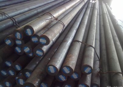
I’ve seen shops spend extra on specialized hot runner molds but still try cutting corners when it comes to base design materials — big mistake. Ever tried getting consistent cycle times with an oversized gate that’s overheating every third shot? That’s why I often sneak some copper bars into specific insert areas.
Copper helps balance temperature across large or intricate cores—particularly useful near slides, angled pins, and ejectors prone to thermal buildup. The best results happen when they're press-fitted into tool steeel rather than welded or screwed on. Bond stays tight for life without maintenance concerns.
How a "Butcher Block" Cooling Design Hurts Production Time
If someone suggests throwing any generic cooling bar into your die setup without flow testing first—that's when trouble begins. Think of your system like veins carrying warmth from fire-heated steel. You want consistency—no cold spots, and absolutely NO turbulence!
"copper sink butcher block". Yep—it’s my inside joke term for setups that throw coolant tubing around without analysis. If the pattern zigzags like a meat block slicing chart, you’ve got issues with stagnation and inconsistent extraction rates.
"Don't trust anyone selling “universal" cooling solutions. Every mold should get its own tailored cooling strategy."
Durability Meets Performance: Material Comparison For Critical Components
Not all components need premium tool steel treatment—some can lean on more conventional alloy or insert pieces, depending on job complexity.
This table outlines which parts justify premium material costs vs. which tolerate standard replacements:
| Mold Section | Ideal Materials | Performance Benefit |
|---|---|---|
| Ejector Plate Core Guides | D2 tool steel | Ride stability under continuous motion friction |
| Cavity inserts (textured surfaces | H13 Nitried steel | Slick surface release & minimal abrasion damage |
| Taper lock / Angle pin areas | Sinterred beryllium copper bars | Fewer cracks from residual tension + conductivity help reduce sticking risk |
Machining Strategies Impact Mold Integrity
No matter your material picks—a sloppy machining setup undoes weeks of effort. We don’t take chances here either; I personally inspect cutter tool path angles before each rough cut session. Especially if the tool steek was pre-hardened past HRC40 mark—which is pretty much standard practice now days. Cutting forces tend to wander, so CAM paths shouldn't skimp on clearance room.
- Balancer blocks added after core placement reduces deflection by 45%
- Z-depth steps in endmilling shouldn’t exceed bit diameter x 2
- Avoid abrupt tool changes mid pocket cuts unless unavoidable—leads to chatter lines on final surface finish
And there you have it—straight from the horse's mouth (my workshop, anyway). Whether you're starting your first mold or scaling a shop for multi-cavitiy output lines, understanding your foundational requirements is vital before rushing into fancy hot runner upgrades or complex core pulling units.
Your die bases hold everything together literally—and figurativvly too: a well-engineered base translates into tighter tolerance control and fewer rejects. Next tieme you consider upgrading one component — think bigger picture, and check that your choice fits cohesively inside a broader, performance-optimized structure.