
Introduction to Die Base with Copper Blocks
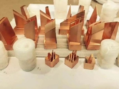
I'm here to help you choose the best die base using copper blocks for your industrial needs. If you work in a heavy-duty manufacturing sector, you might have run across this type of equipment before. Die bases are foundation platforms for tooling applications. But once you add block of copper inserts into the system — things can perform differently than you may expect.
- Increased electrical conductivity when designed correctly
- Precise temperature control
- Enhanced durability under high-stress cycles
| Copper Embedded Die Base | Conventional Die Base |
|---|---|
| Better wear resistance | Deteriorates more rapidly |
| Superior thermal dissipation | Tends to hold heat longer |
| Moderate increase in up front costs | Likely more upfront cost-efficient |
Pro Tip::
Metal Characteristics and Material Compatibility
What I really look out for when evaluating copper integration is how well it blends with surrounding materials in the die frame. Pure oxygen-free copper has higher malleability, but not every industrial die press demands those specs right away.
A quick note on common material clashes:
Steel alloys may expand at different rates

Casting metals sometimes resist full bonding

Plated finishes tend flake easier next to unsealed copper
The most successful setups often involve hybrid systems that let both the copper’s conductive properties shine while still allowing structural steel dominance where needed. It's something to talk through during pre-maintenance rounds too.
- Copper expands ~50% faster than tool steel
- You need special adhesives and soldering methods
Vinyl Base Molding Integration Challenges (and Solutions)
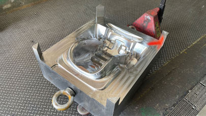
One area many ignore? Vinyl Base Molding. That’s especially when interfacing vinyl or composite linings along die edges. Those areas demand thermal isolation without causing friction-induced damage — which makes strategic insertion of block(s) of copper crucial to regulate temperatures evenly along the form surface.
- Analyse existing base molding points
- Create custom channel grooves in copper sections
- Run simulated compression tests before production launch
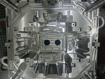
Finding the Right Dimensions and Load Ratings
After decades handling various presses from CNC to manual toggle types, my experience says matching load capacities with the die design remains underrated in guide posts.
- Understand total cycle pressures over long time frames (e.g., after every few weeks continuous run time)
Total Force = Area × Unit Pressure of Material × Safety Buffer (20–25%) - Suitable copper thicknesses vary from 0.125" to nearly ½" thick based on expected mechanical impact frequency
Thinner copper inserts respond better to sudden changes during cold startup phases but may not be enough past a million-cycle threshold
A 7-ton hydraulic die stamping operation will probably handle a copper core just fine.
But try scaling down to micro components — there, even minor variances show up as dimensional drift.
Maintenance Considerations Across Production Cycles
- Annual inspections for copper integrity highly recommended
- Schedule regular calibration checks on thermocoupled regions if applicable
- Note visual inspection patterns: dislocation streaking usually indicates internal stress fracture risks ahead
Pitfalls With Cutting and Modifying Custom Die Base Designs
Now — a major problem arises whenever folks attempt cutting base moldings directly near copper regions using standard blade profiles. The result? Uneven edge wear due to the copper pulling against typical carbon-fiber reinforced blades. This creates jagged or slightly wavy cuts depending on the depth applied during trimming. To combat this:- Select diamond-etched grinding discs where necessary
- Use low-speed cutoff methods (<12,000 RPM recommended)
- Multiply coolant applications at blade interface points
| Tool Type | Makes sense here? | Durability Notes |
|---|---|---|
| Tungsten carbide tip saws | Copper tends melt blade tips easily — avoid | |
| Epoxy-bond diamond discs | Best choice for copper-embedded cuts | Last long with steady lubrication |
| Wire EDM | Ideal where precision counts above efficiency | Hugly precise but slow — only practical for critical junction shaping needs |
Cost/Benefit of Hybrid Versus Fully Metal Systems
In some cases people want an entire die core fabricated entirely of pure OFHC-grade copper. But reality bites hard here – while copper does transfer heat better, you don't get massive gains without huge investment increases. Especially when running short batches with minimal tool wear per unit.What works far better:
- Copper “hot zones": Inserted just into contact regions with extreme thermal cycling
Example areas include cavity runner channels and mold sprue openings. - Composite die blocks: These use pressed graphite or bronze-copper matrix panels inside a hardened casing for optimal value-performance tradeoff
Common Questions Asked by Industry Peers
While doing plant walkarounds, these topics arise often: Q. Is die life improved using copper embedded parts?A. Only when dealing with specific application factors including sustained elevated temperatures or repeated impact cycles. You should compare current maintenance records to determine actual ROI potential for any retrofit project you consider. Another one heard frequently: Q. Can i drill into existing block of copper inserts during modifications?
Short answer: YES… with caveats.
- Speed matters (low is safer here).
- Select bits rated specifically for metalwork rather than multipurpose or woodcutting ones.
I maintain contact details on companies who offer full-scale machining plus copper bonding facilities nearby US production hubs. Hit up a specialized engineering procurement office or request support via the NADCA network (North American Die Casting Assoc). Also explore local casting manufacturers familiar with ISO 14938: Industrial dies safety regulations around conductive component placement during build phases.