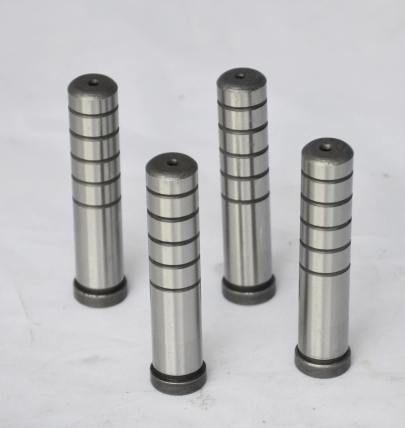
Mold base diagrams are an essential component in the manufacturing industry, particularly in injection molding and tooling. These diagrams provide critical information for the design and assembly of mold bases, ensuring that manufacturing processes are efficient and effective. In this article, we will delve into the intricacies of mold base diagrams, their components, the benefits they provide, and key insights into their role in enhancing manufacturing efficiency.
What is a Mold Base Diagram?
A mold base diagram is a technical illustration that outlines the design specifications and operational requirements of a mold base. It includes detailed representations of various components, dimensions, and materials used in the construction of the mold. The primary objective of a mold base diagram is to facilitate the communication of design intent between engineers, designers, and machinists.
Key Components of Mold Base Diagrams
Mold base diagrams encompass several key components that are crucial for successful manufacturing:
- Mold Plates: The foundation of any mold, typically made of steel or aluminum.
- Cavities: The hollow sections of the mold that form the shape of the final product.
- Core Pins: Components that help shape internal features of the molded part.
- Cooling Channels: Pathways designed for regulating temperature during the molding process.
- Mold Inserts: Replaceable components that allow for quick changes in part designs.
Importance of Mold Base Diagrams in Manufacturing
Mold base diagrams play a pivotal role in various aspects of the manufacturing process. Their significance can be summarized as follows:
| Aspect | Description |
|---|---|
| Design Accuracy | Ensures that all components fit together precisely, reducing errors. |
| Cost Efficiency | Reduces waste by optimizing material usage and fabrication processes. |
| Improved Communication | Enhances collaboration among design, engineering, and manufacturing teams. |
| Streamlined Production | Facilitates faster turnaround from design to production. |
Best Practices for Creating Mold Base Diagrams
Creating effective mold base diagrams involves adhering to specific best practices:
- Utilize industry-standard symbols and annotations to ensure clarity.
- Maintain consistent scales and dimensions to avoid confusion.
- Incorporate detailed notes regarding tolerances and material specifications.
- Ensure that all cooling and heating needs are clearly marked.
- Review and validate diagrams with team members to eliminate errors.
Common Mistakes to Avoid in Mold Base Design
While creating mold base diagrams, several common pitfalls should be avoided:
- Neglecting Cooling Requirements: Failing to properly plan for cooling can lead to defects in the molded products.
- Ignoring Tolerances: Not specifying tolerances can result in parts that do not fit correctly.
- Overcomplicating Designs: Complex designs may lead to increased manufacturing costs and longer lead times.
Technological Advancements Impacting Mold Base Diagrams
With continual advancements in technology, mold base diagrams have also evolved. Some notable innovations include:
- 3D Modeling Software: Facilitates the creation of three-dimensional representations, providing clearer visualizations of mold designs.
- Simulation Tools: Allow designers to simulate how the mold will operate under various conditions, optimizing performance before fabrication.
- Collaborative Platforms: Enable teams to collaborate in real-time, improving design accuracy and efficiency.
Conclusion
Understanding mold base diagrams is crucial for anyone involved in the manufacturing process. These diagrams not only enhance communication among teams but also significantly impact the efficiency and effectiveness of production. By following best practices and staying informed about technological advancements, manufacturers can leverage mold base diagrams to optimize their operations.
FAQs
Q1: What materials are commonly used for mold bases?
A1: Mold bases are typically made from materials such as steel, aluminum, or other sturdy alloys, depending on the application's requirements.
Q2: How do cooling channels affect the molding process?
A2: Properly designed cooling channels help maintain the right temperature during molding, which minimizes cycle times and reduces product defects.
Q3: Can mold base diagrams be modified after production starts?
A3: Yes, modifications can be made, but it’s essential to analyze the impact on existing designs and processes to avoid complications.


